Cantilever Post Deflection (Post and Bracket)
Let’s look at a post, say in a shop, or a barn, acting as a vertical cantilever. This means that the base of the post is held rigid (not allowed to rotate), while a lateral (horizontal, or sideways) load is applied, say, to the top. And let’s see how much the post bends, resulting in lateral (essentially horizontal, or sideways) movement of the top. Engineers typically call this movement `deflection’. There’s a standard engineering formula we can use to calculate this deflection, specifically,
Δ = P L3 / (3 E I),
where
Δ = how far the top end moves (deflects), in this case, horizontally,
P = the horizontal force, applied at the top,
L = length (height) of the post,
3 = the number 3 (`three’),
E = the modulus of elasticity of the post material, and
I = the moment of inertia of the post (a function of the post cross section and orientation).
Suppose the shop has walls 9 feet tall, the posts are in the walls, and that trusses are attached at ends to the tops of the posts, the trusses span 40 feet, and the roof slope is 4/12.
The trusses, and supporting posts, are spaced 8 feet apart.
Further suppose that the force involved is a wind force hitting the shop from the side. Let’s look at the wind force involved trying to push over an 8-foot-wide `swath’ of the shop, including windward wall, leeward wall, and 8-foot-wide swath of roof, being kept from blowing over by the `frame’ action created by the truss and pair of posts at ends on opposing walls.
Let’s assume the framing of the structure takes the wind pressure forces acting on the bottom halves of the windward and leeward walls to the ground, circumventing the posts. And let’s assume that the wind pressure forces acting on the top halves of the walls (via girts, or whatever), and swath of roof, are delivered to the tops of the posts (at the roof/wall line).
The total horizontal force delivered to the `swath’ walls and roof, and, in this case, delivered to the cantilever posts, is, say, 400 pounds (lb), which we will assume divides equally, to 200 lb, to each of two posts (windward and leeward).
(See here and here for an example calculation on a similar structure, but with different wind design parameters.)
Now let’s say we are using a 6 x 6 Douglas-fir wood post, Grade No. 2, for which E = 1,300,000 pounds per square inches (psi), and I = 76.3 in.4 (both values from the National Design Specification® for Wood Construction Supplement).
Before we drop the above `ingredients’ into our `standard formula’, let’s get the post height into `inches’;
L = 9 feet x 12 inches / foot = 108 inches (in.).
Δ = P L3 / (3 E I) = 200 lb (108 in.)3 / (3 x 1,300,000 psi x 76.3 in.4 ;
Δ = 0.85 inches. (Almost 1 inch.)
If you were sitting on the eave line, and could ignore the wind that would be causing this force, you would certainly feel this movement.
If the shop is really long, the whole building would essentially experience this lateral movement, sway.
If the building is not really long, then the roof would act as a `diaphragm’ … a long, flat, thin, horizontal beam, and as the building starts to sway, the top of the post would engage the stiffness of the roof, and some of the force would be carried through the plane(s) of the roof to the end walls. The amount of wind force carried by the posts, versus the amount carried to the end walls, relates to the relative stiffness of the roof (as a diaphragm) and the (stiffness of) the posts. `Load goes to stiffness.’ Really stiff posts – the wind load will be carried by the posts. Really stiff roof, and end walls – the lateral load will be carried by the roof and end walls. Most real buildings fall somewhere in between. We’ll discuss this in another post.
But there’s more to the sway of the post than the pure `bending’ of the post itself. If the post is embedded in a concrete pier, the concrete pier probably holds the post pretty `rigid’ (as long as the pier itself doesn’t move). If the column is attached to the pier, or other type of foundation, with some kind of metal `bracket’, we need to look at how `rigid’ the bracket is. And the answer probably is, `not very’. Typically, wood connections, being wood-to-wood or wood-to-metal, are not relied upon to provide rigidity, though the attempt at making such brackets is not new, and is in fact, ongoing. The only real `tried-and-true’ rigid wood connection is the so-called `Moment Splice’; see Chapter 15 of the Timber Construction Manual, Sixth edition, by the American Institute of Timber Construction. This connection is not what you would see at the base of a post for a shop, or barn.
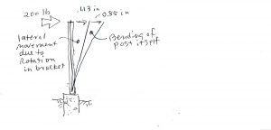
Supposing, though, hurdles cleared, a rigid (`moment’) connection is found for the 6 x 6 post, for installation in concrete, and that it has a stiffness of (I’m just picking a number, but not terribly dissimilar from what you might find `published’ by a manufacturer) 3,000 lb-ft / degree. This means that a `moment’ of 3,000 lb-ft exerted by the post on/in the bracket, will cause the post to rotate, in the bracket, 1 degree of angular measure. In the example above, we’re looking at a moment of 200 lb at the top of a 9-ft post, or, about 1,800 lb-ft. Thus, the bracket will rotate … 0.6 degrees. The post comes out of the bracket at an angle! The angle is not a big one, but watch! This angle is magnified by the length (height) of the post. The top of the post, just per the angular rotation, moves, laterally, 0.6 degrees times π rad per 180 degrees … times 108 inches, or 1.13 inches. The total movement of the top of the post is the sum of that produced by rotation in the bracket, plus the bending of the post itself, … 0.85 inches plus 1.13 inches, or 1.98 total inches … almost 2 inches. (Pick your bracket carefully!)
It is interesting that, in this example, the lateral movement of the top of the post is due more to the bracket than the bending of the post itself.
And, again, note that in any `real’ building, the top of the post will have engaged the `diaphragm action’ (resistance) of the roof system itself, long before this calculated deflection, or lateral movement, meaning that the post will not take on the full 200-lb load, and nor will the top end deflect the full 2 inches. How much, or how not much, depends on the stiffness of the roof.
+++++
Rotation of the post in the bracket might result from any number of effects, such as crushing of wood by the fasteners and in bearing with the bracket metal, oversize fastener holes, gaps between wood and metal due to poor fit and/or shrinkage, and metal deformation.
+++++
Also note that this assumes no movement (rotation) of the foundation itself, where it is assumed that the bracket is in some way attached to or embedded in concrete. If the concrete is a concrete pier, then attention should be paid to how much the concrete pier might rotate in the founding or backfilled soil. Seriously.