Wind Load on a Shop Using ASCE 7-22 (Envelope Procedure) – Part 2 (Horizontal Force)
Continuing from Part 1 …
Step 6: Determine the external pressure coefficients, GCpf … Section 28.3.2.
For Case 1 we get … roof slope tan-1 4/12 = 18.4° … interpolating between 5° and 20° …
|
interp |
|||
|
GCpf |
per |
||
|
slope, deg |
actual |
||
|
Zone |
5 |
20 |
18.4 |
|
1 |
0.4 |
0.53 |
0.52 |
|
2 |
-0.69 |
-0.69 |
-0.69 |
|
3 |
-0.37 |
-0.48 |
-0.47 |
|
4 |
-0.29 |
-0.43 |
-0.42 |
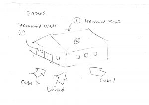
Note that the positive coefficient for Zone (1) and the negative coefficient for (4), are, as far as the frame (bent) is concerned, `additive’; both tend to push (`flop’) the frame over.
The coefficient for Zone (2), the windward roof plane, is interesting. The negative sign means suction (`away’ from the surface). This pressure actually counteracts the lateral (horizontal) wind effects on the wall. It begs the thought of a `negative’ wind drag force. In fact, if one looks at the pressure distribution on an airfoil (this low-rise shop is kinda like an airfoil), there is a zone on the upper front of the foil where the pressure does indeed act `upstream’! But, for both the airfoil, and any building, any `upstream’ effect is presumably wiped out by the other, `downstream’, effects, such as on the rest of the surfaces.
It is also interesting to note the coefficients for Zones (1) and (4) for Load Case 2, wind hitting the end walls. In Case 2 the side walls experience negative pressure (suction), and the building wants to `explode’. We are not looking at that effect in this post; just the flopping over from net force pushing on the windward (side) wall, wind going over the roof like a foil, and sucking on the leeward (side) wall.
Note further that we are not looking at the ends of the side walls and roof (Zones 1E, 2E, 3E, etc.); we can look at those later. Right now we are getting the lateral force(s) for the interior (between-the-ends) transverse frames (bents).
Step 7: Calculate the wind pressure, p, from Equation 28.3-1 …
p = qz Kd [(GCpf) – (GCpi)] … for each surface.
Without proof here, and per the symmetry of the frame (bent), I state the following: as far as the frame (bent) is concerned (an 8-ft wide swath through the building), the internal pressures cancel out for the walls, and, for the walls, we will look at the `sum’ of the external pressures. For the roof surfaces, I only need to look the `sum’ of the roof pressures as acting on a vertical projection of the roof volume. Here goes:
Wall(s): p = qz Kd GCpf windward (Zone 1) – qz Kd GCpf leeward (Zone 4) =
p = qz Kd (GCpf windward – GCpf leeward) =
p = qz Kd (0.52 – (-0.42)] =
p = qz Kd (0.94).
Aside from the Kd term, the net horizontal pressure is (94%) that of `stagnation’ pressure.
p = 18.5 psf (0.85)(0.94) = 14.8 psf.
This force acts on an 8-ft wide swath of the windward and leeward walls, with (projected) area equal to:
A = 8 ft x 8.5 ft = 68 square feet (sf).
The total (net) force acting on the walls (pushing on the windward and sucking on the leeward) is, thus,
F = p A = 14.7 psf x 68 sf = 1,000 lb.
Oh, wait! The walls are no doubt attached to some kind of sill, at the ground (foundation); so let’s say that half of the wall force goes up to the eave, and half goes to the ground. Therefore, the force from wind action on the walls, acting at the top of the wall, is
F = 1,000 lb / 2 = 500 lb.
NOW FOR THE ROOF …
p = qz Kd (GCpf Zone 2 – GCpf Zone 3) =
= qz Kd [(-0.69) – (-0.47)] =
= qz Kd (-0.22) … whoa, yeah, the `negative drag’ effect …
= 18.4 psf (0.85) (-0.22) = -3.4 psf … again, I wish I didn’t have 0.85 for two different effects.
The vertical projected area of the roof is … 8 ft wide x 6.67 ft tall, or 53.4 sf.
F = p A = -3.44 psf x 53.4 sf = -183 lb.
The total horizontal force on the frame (bent) is …
Fx = 500 lb – 183 lb = 317 lb.
But, we need to look at Section 28.3.3. It requires that the total horizontal force not be less than that determined without the pressures on the roof. So, while this `negative drag’ on the roof might be in some sense real, it should not be counted on, and, in other cases, perhaps doesn’t exist … these provisions and requirements, remember, are part of the `envelope procedure’, intended to capture a whole range of possibilities and geometries. We’ll talk more about this `negative drag’ in another post.
So, the total horizontal force is … 500 lb.
Let’s divide this equally to the ends of the trusses/tops of the posts; the lateral (horizontal) force at the top of each post is thus,
Fx, top of post = 500 lb / 2 = 250 lb, each.
We’ll see that this is not very much compared to the vertical (uplift) forces on the roof (and posts).
(Stay tuned for Part 3 … the vertical (uplift) wind load on the shop … in progress.)
*****
And on roof overhangs (28.3.5) … here (forthcoming)
And on `Minimum Design Wind Loads’ (Sec. 28.3.6) … here (forthcoming).