headers without engineers
( … long post …)
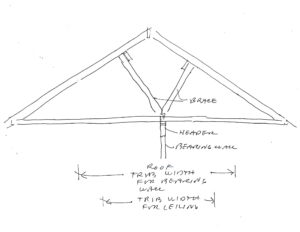
Consider a conventionally-framed house facing a remodel project. The house is, for the most part, a simple, two-story `box’, with stick-framed roof and interior bearing wall. The interior bearing wall supports both roof and main story floor. Two walls are to be removed per the remodel; one wall is a segment of the interior bearing wall, and the other a non-bearing wall. The interior bearing wall runs longitudinally through the house, roughly down the `middle’. Ten or so feet of the wall are to be removed, opening up the dining room to the kitchen. The segment to be removed, being on the main floor, supports only the roof and ceiling. The non-bearing wall to be removed is between present dining room and living room. Non-bearing walls will be discussed separately. The idea here is to see how we can determine what kind of beam, or header, is needed, to carry the roof and ceiling over this new space, created by removing a part of the bearing wall. A cross-section sketch of the house framing is shown below.
The `easiest’, and perhaps most expensive, way to determine what we need, is to `hire an engineer’. I am such a person. But why? I’m retired (mostly), and since the house was originally designed without an engineer, as are many, why hire an engineer to help with a remodel?!
First, let me say, that you may have to hire an engineer. Second, you may want to hire an engineer, whether or not you `have’ or `need’ to. Let me explain. A bearing wall is a `structural’ part of the home; it holds part of the home up. Do it wrong and your house may collapse, or look like it’s collapsing. You may want to hire an engineer, just for peace of mind. You may have to hire an engineer … if the building regulations for your locale require it! This would typically come about via the permit process. You may want, or have to, get a building permit to do the remodel. And to be granted the permit, if dictated by the building official, you may have to hire an engineer. In some cases the local building official himself/herself might determine what kind, size, etc. header is needed, or might have design aids for such, but don’t count on this1.
The contractor you choose to do the work (if not yourself) might be willing to determine, or `size’, the header for you. Careful with this one, unless he or she plans to hire an engineer, and pass the associated fees as part of the remodeling contract. While good contractors can do amazing things with buildings and building materials, they typically do not have the science background to properly `engineer’ a solution. And by this I mean a long-term solution … a header that will hold up the roof, not only for the duration of the construction project, but for the `life’ of the structure itself. But, again, if we can come up with a solution without hiring an engineer, let’s do it. And if a permit is required, perhaps your`non-engineered’ solution will make enough sense to the building official, that he / she agrees, and issues the permit. (Yay!) After all, all the headers in the existing building got past having to involve an engineer; why not one or two more!?
Let’s look at some ways to do so.
1. Provisions in the International Residential Code (IRC) … online version here. I will be referring to the 2018 edition. Further, the IRC was likely the basis of the building code governing your original structure when first built anyway (if governed at all).
R602.7 Headers. For header spans, see Tables R602.7(1), R602.7(2) and R602.7(3).
Table R602.7(1) is for exterior walls … R602.7(2) is for interior bearing walls … and R602.7(3) is for open porches.
The problem with Table R602.7(2) is that it doesn’t seem to accommodate any roof load.
Let’s look at Table R602.7(1) … and … R602.4 …
R602.4 Interior load-bearing walls. Interior load-bearing walls shall be constructed, framed and fireblocked as specified for exterior load-bearing walls.
So, let’s use Table R602.7(1) to come up with our header. I suggest that the braces direct the roof load in such a way that the interior bearing wall carries more than half of the roof … all of the roof between the braces, and half the spans from braces to exterior walls, or, 5 feet between the braces + ½ of ½ of (30 – 5) on the left and ½ of ½ of (30 – 5) feet on the right, or … 5 + 2 x ½ x 12.5 = 17.5 feet (ft) (of building width). This would correspond to an equivalent (more simple) building width of … 2 x 17.5 ft = 35 ft. We’ll use the first set of `spans’ in Table R602.7(1) … `headers supporting roof and ceiling’. The house is in a region of `no snow’, so, per footnote e to the Table, we’ll use the 30 psf Ground Snow Load. Recall that we want an opening (span) of (about) 10 ft. For a building width of 36 ft we get … 4 – 2 x 12s give us 9-10 (9 feet 10 inches). We should also look at the footnotes, but, before we go any farther … note the `4’. This means FOUR 2 x 12s, each of which is 1.5 inches thick … or a header of 4 x 1.5 = 6 inches. The resulting header will be 6 inches wide (thick) by almost 12 inches deep. That will be hard to hide in an interior bearing wall. Yeah, our building `equivalent’ width is 35 ft, not 36, so maybe we could split some hairs and go a bit smaller (by `interpolating’, per the footnotes), but we won’t be able to reduce it (the header requirement) by much. Even if our building were only 24 feet wide, the requirement (without the weird braces) would be 3 plies of 2 x 12s. Yikes. (That’s why big openings in bearing walls in conventional construction are rare.)
2. Let’s look at provisions in the International Building Code (IBC) … online version here.
Chapter 2308 of the IBC addresses conventional light-frame construction … (our stick-framed house) … but we end up in the same dilemma, exactly … 4-ply 2 x 12s. See Table 2308.4.1.1(1). Ugh.
3. Try the Wood Frame Construction Manual (WFCM), which is referenced in the IRC, as applicable to (usable for) residential construction (per Section R301.1.1).
Same issues … we don’t see anything directly giving us a solution for an interior bearing wall carrying roof/ceiling only. Tables 3.22A1 and A2 give us options for exterior wall, roof/ceiling only, with the difference in the Tables being dropped header, or raised. A dropped header has a top somewhat below the wall top plates, necessitating cripple studs, which can’t be counted on as providing so-called lateral stability for the top of the header (I’ll explain elsewhere). A raised header is mounted right up under the roof/ceiling construction, stabilizing the top of the header, and is the case of the remodel considered. So we’ll go with A2 … and we see `solutions’ such as 4 – 2 x 12s, roof live load 20 psf, can span 10-8, for building width of 36 feet. We also see 4 – 2 x 10s can span 9-1, and so on … not a whole lot different than what we got with the IRC and IBC.
Big opening … big header required.
Oh, the Wood Frame Construction Manual is also available online … here. (I link to the 2018 version, but newer is available, as per the IRC and IBC.)
Let’s look at WFCM Chapter 2. Chapter 2 gives us loads and stresses, instead of specifying the actual header makeup. Look at Table 2.11, upper right. There’s an interior bearing wall holding up roof only! Yay! For a roof live load of 20 psf, building width of 36 feet, the Table gives `720’. This is the unit load on the header or beam or girder. For a building width of 24 feet, we get 480. Going back to the 36 width, then, the 720 means that each foot of header (length), no matter how long, carries 720 pounds. If the header is 10 feet long, the total amount of roof/ceiling load is 720 x 10 or 7,200 pounds (lb). This 720 unit load is also called a `line load’, or pounds per lineal/linear feet, or plf, etc. This doesn’t help us much directly, but can be tremendously useful as we look to some further tools. This number enables us to `engineer’ a header.
Note that if we had a shorter amount of wall removed, we’d be done … try 6 feet in the examples above. Go back and look at Table 3.22A2 in the WFCM … a 2-ply 2 x 10 would carry an opening of 6-3 in a 36-ft wide house. Looking at IBC 2308.4.1.1(1) we see a 2-ply 2 x 10 can carry 5-9, and 2-ply 2×12 … 6-10. Perhaps the difference is that the 2308.4.1.1(1) uses 30 psf snow load for both it and 20 psf live load. And perhaps an eave is considered. Or perhaps there are other effects mixed in (wind?) We’d look closer at the line items in the Manual (or code), and perhaps Commentary(s), if the 6 foot opening is really what we are designing. The IRC comes up with the same thing as the IBC.
4. Design aids provided by industry / manufacturers.
Already you might have realized, justifiably, that dimension lumber isn’t going to work, unless we want a fat header. So let’s look to `engineered’ wood. There are several options. We can go with structural glued-laminated timber (glulam), or structural composite lumber (SCL). And there are others. But, sticking with either glulam or SCL, let’s see what we can find. Let’s see what the glulam people have to offer … the American Institute of Timber Construction (AITC) (on www.aitc-glulam.org). (You’ll get redirected to www.plib.org/aitc as AITC was absorbed by the Pacific Lumber Inspection Bureau (PLIB), and the West Coast Lumber Inspection Bureau (WCLIB) along the way.) Look under Resources, then Publications … and then Southern Pine, and then Roof Beam Construction Load. (Construction load governs where snow loads don’t … consider it the Roof Live Load.) And let’s open up SP 26F – 1.9E, and we have options. Looking at a span of 10 feet … and something that carries (at least) 720 plf, we see … 3-1/8 x 8-1/4 carries 768 B. The `B’ means bending (stress) controls. Whoa, nice … the 3-1/8 width certainly fits in the 2×4 interior bearing wall dimension. And 8 inches is pretty modest. But, we’re not done; we need to be a bit careful. The Table says that the deflection limit is Span/180 for total load. Deflection is a different conversation. But, for now, let’s look back at IRC Section R301.7 and Table R301.7. The Table indicates a deflection limit of L/240 for members supporting flexible finishes, including gypsum, and R301.7 says the limit is based on the … live load of Section R301.6. There is a disconnect … L/180 for `total’ from AITC, and L/240 for `live’ (our construction load) from IRC. We can reconcile the two using Table 1604.3 of the IBC … which relates the L/240 for live load and L/180 for live load plus dead (equaling total).
So, a 3-1/8 x 8-1/4 SP 26F-1.9E (Southern Pine) glulam beam is adequate for the header! (Show that to the building official.)
Now note! … these answers are bare-bones minimums! The AITC Table indicates that the `solution’ is based on bending stress (the `B’). But if we look one column to the right, for the same beam, and an 11-foot opening, the allowable load is 618, and `D’ … that means it’s deflection-controlled. I would argue that the 10-foot span is `almost’ deflection controlled. That would mean that, under the 768 plf, the beam would be expected to have a total deflection of `Span divided by 180’, or 10 feet x 12 inches per foot / 180 = 0.67 inches … about 5/8 of an inch. It might `meet code’, but is that really what you want (to see) above the opening between the kitchen and dining rooms? You might want it to be less, maybe way less! What if we want to drive it down to, say, ¼ inch total. Well, a wood beam is like a spring. We would need a heavier (stronger) spring. Look at the 3-1/8 x 11; it can carry a load of 1365 plf, and is controlled by bending stress. That suggests that, under the 1365, the deflection is not yet at the (Span /180) limit. Maybe significantly under the limit. Since the 3-1/8 x 11 also acts like a spring, under only 720 plf instead of 1365, it would have a total deflection of not greater than 0.67 x 720 / 1365 = 0.35 inches. (Half the load … half the deflection!) Actually less (since bending controls the 1365, not deflection). Maybe way less. (The actual engineering `calc’ not shown.) Turns out to be almost exactly 0.25 inches. Sweet. Generally it’s not a problem going stiffer and stronger than the code minimum(s). Obviously the 11-inch beam will cost more (and weigh more). In a remodel the only issue that we might run into with a deeper beam is `headroom’ … make sure there’s enough clearance under the beam / header to `meet code’ (and your needs … maybe you’re a tall person!).
Let’s try a different product … say Laminated Veneer Lumber (LVL), a type of SCL.
I found that a Roseburg 2-ply 1-3/4 x 9-1/4 2.1E will carry 1307 total (non-snow) load over 10 feet. The 2-ply 1-3/4 is sweet, as the total thickness will be 3.5 inches … perfect for an interior wall (typically 2×4 nominal). Engineered lumber is typically stronger, and stiffer … alas the smaller dimensions. (In the project considered, 2-ply 1-3/4 x 11-1/4 2.1E LVLs were used, and the opening enlarged a bit, to 11 feet). Note that when selecting engineered lumber, you need to make sure it’s `available’ in your locale. Actually, it’s the same with dimension lumber, when dealing with specific species and grade. Southern pine lumber, and engineered lumber made from Southern pine, is generally available on the `South’ (east); Douglas fir, and products made from Douglas fir, are available in the West. And/but there are other lumber species … Hemlock, other firs, cedars, and so on, and some lumbers are `mixed’, e.g., hem-fir, which is a mix of Western Hemlock, and firs. (Just make sure what you want is available, or, find out what’s available, and design within.)
5. Some straightforward calculations and common sense.
Go back to the discussion above where we jump into Chapter 2 of the WFCM, specifically, Table 2.11A. Note the Table heading says Roof Assembly DL (Dead Load) = 20 psf. This is the assumed weight of the roof and ceiling materials (including insulation, whatever). Under RLL (Roof Live Load) of 20 psf, and following the 36-foot width over to the upper right, where it shows a header (or beam) carrying the middle of the roof, we got (get) 720 plf. If we go up to 24-foot building width, we get 480 plf. Now let me show you something. Maybe you already see it. We could say this header (the one in the WFCM graphic) carries half the roof. Or we could say that it carries half the way from the peak to the exterior wall, both directions. Same thing. For a building width of 36 feet, the interior header (or wall) carries an 18-foot wide `swath’ of roof (9 feet each side of the ridge). Each foot of wall (or header) length thus carries 1 ft x 18 ft or 18 square feet of roof. If the roof weighs 20 pounds per square foot (psf), then the wall (or header) carries 18 x 20 = 360 pounds of roof, per foot of wall (or header). Similarly, if the live load on the roof is 20 psf, each foot of wall (or header) carries 360 pounds. Add the two together, and the header (or wall) carries 720 plf, under the design condition of dead weight (or course), and live (probably a re-roofing crew). Yeah, it’s that easy! Similarly, for a building width of 24 ft, the interior bearing wall (and any headers therein) carries ½ of 24 ft x (20 + 20) psf = 480 plf. Determining weights of the material of the roof (dead loads) is not particularly difficult, and the design loads (live, snow, etc.) are typically provided by the local building code … so sizing any header, now, unless the building is unduly complicated, is … doable!
Let’s say we have a building that is 32 feet wide, and the roof is constructed of pre-manufactured trusses (allowed in the IRC, IBC, etc.), that span wall-to-wall. Let’s say we have a design snow load of 60 psf. And we determine that the roof weighs no more than 15 psf. Oh, and let’s add 12-inch eaves. Each exterior wall carries ½ of 32, plus 1 ft, or 17 ft. The total load on the exterior wall (and any headers therein) is 17 x (60 + 15), or 1275 psf. Let’s go back to the AITC Beam Capacity Tables, but this time find one for beams made of Douglas fir, and let’s say we have an opening of 12 feet. Table AITC DF-26 Roof Beams Snow Loads … the 3-1/8 x 12 will carry 1497 plf for 12 feet. Alternately, the 5-1/8 x 12 will carry 1572 plf for 12 feet. Either would work. The 3-1/8 x 15 weighs 11.4 pounds per foot, and the 5-1/8 x 12 weighs 14.9 pounds per foot. Other things equal, the heavier beam will likely cost more. On the other hand, if we’re fighting 60 psf of snow, we’re probably also dealing with 6-inch exterior walls; the 5-1/8 inch wide beam might fit better. Ask the manufacturer; they may well offer widths of 5.5 inches, fitting even better in 2×6 walls. Notice again that the deflection limit is L/180; we could go wider or deeper to get an even `bigger’ (stiffer) beam with less deflection. Notice also that both sizes are controlled by bending stress; thus we know that the deflections will be less than the L/180 … how much less we don’t know without some more work. Finally, and importantly, the footnotes indicate that the beams must be supported laterally along the top. This is typically by attachment to a double top plate to which the trusses are attached … holding the top of the beam in place, from buckling out of the plane of the wall. This is the `raised’ header. If the header is lower, a `dropped’ header, with cripple studs from header to the top of the wall, the beam is, strictly speaking, not laterally supported, and there will be lessened bending capacity. A `bigger’ beam may be required. But the bigger beam will give us more deflection control. Some design aids accommodate for the dropped header, either by providing additional tables, such as we saw in the WFCM Chapter 3 Tables, and some aids provide adjustment factors for the tabular values. Otherwise more difficult (`engineering’) calculations may be necessary to deal with the unbraced beam condition. And, of course, make sure this beam is even available in your locale.
So, with this start, you can see some ways to `design’ a header for an interior load-bearing wall. The idea was to avoid hiring an engineer for what are typically non-engineered buildings (residential construction). And we could take what we did here as a start into a plethora of additional ways to design headers … using various online resources, calculators, software, and so on. We could have switched over to steel, and specified a steel beam for the header. Switching to steel might be the only way to deal with high loads and long spans. And, interestingly, though not surprisingly, if you think about it, various manufacturers have design aids by which you can `switch’ from one material to another (typically their material) … say a parallel strand lumber (PSL) beam (a type of SCL), to glulam. Or steel to glulam, or … the information out there is endless. No doubt, somewhere, is a table trading dimension lumber for SCL.
At some point, yeah, hire an engineer.
1If it is necessary to involve the building department, make the building official your friend. Who knows what he / she might come up with to assist you on your project.