Minimum Design Wind Load – ASCE 7-22 Section 28.3.6 (Envelope Procedure)
In our earlier posts we determined the horizontal and vertical components of wind load on a `shop’ (here). The horizontal force was/is 500 lb, as acting on an 8-ft wide `swath’ of shop, which is framed with wood trusses at 8 ft o.c., on wood posts/columns, spaced 8 ft o.c., in the side walls. The idea is that the force would be applied to the top-of-column-end-of-truss `joint’ … in the analysis of of the columns, trusses, and eventual load path(s) through columns and roof, to foundation. The assumption was made that, for the truss-column-roof analyses, the wind loads on the walls would go straight (down) to the bottom plates, girders, whatever, and not through the column-truss-roof framing and any diaphragm action. Thus, only half of the load on the walls was considered. If (when) we consider all of the wall, i.e., to determine the total horizontal load on the `swath’, we found that the load is 1,000 lb. (Interestingly, it is just doubled, since the minimum load (Section 28.3.3) came about by neglecting the (`negative’) horizontal load from the roof.
It may be a bit premature, but let’s also look at Section 28.3.5 `Minimum Design Wind Load’. It’s not clear whether we should consider this at `each frame’, or the entire structure as a whole, or maybe even `piece-by-piece’. Anyway, we’ll look at it now.
Section 28.3.5 requires that the minimum design wind pressure used in the design of the MWFRS … be not less than the wall area multiplied by 16 psf and a pressure of 8 psf applied to the roof area projected onto a vertical surface. (Perhaps the use of singular `MWFRS’ answered the question above.) Let’s do it.
Wall area: 8 ft wide x 8.5 ft tall = 68 sf
Horizontal force from wall = F = p x A = 16 psf x 68 sf = 1,088 lb.
Roof area: 8 ft wide x ½ of 20 ft x 4/12 = 8 x 6.67 sf = 53 sf.
Horizontal force from roof = 8 psf x 53 sf = 427 lb.
Total horizontal force = 1,088 + 427 = 1,515 lb, say 1,520 lb.
Note that the contribution of horizontal force from the wall(s) didn’t change much.
The big difference is the contribution from the roof … another 500 lb.
My `guess’ is this: the pressure coefficients in 28.3-1 (Load Case 1) capture the effects of the wind blowing over the structure with the structure acting as a (rather strong) air foil … so much so, that, roof alone, by calculation, the horizontal effect is actually negative.
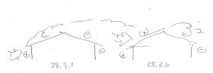
Two Different Air Flows Across Shop
Section 28.3.3 makes sure that we don’t have a negative effect. Section 28.3.6, I suggest, captures the fact that in the turbulence (chaos) of the design wind event, there may be, or are, gusts that exert positive pressure on the windward roof slope … the wind separates’ from the roof at the roof, instead of the windward eave.
*****
The question remains, at least in my mind, should I have done this calculation at this stage (per `frame’, or `swath’), or on the entire structure?