a truss for Miles
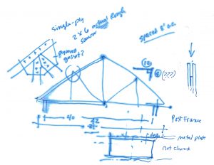
Miles asked me to design a truss for his shop. I grabbed my clipboard. Wood? Yes. Rough sawn? Yes. Rise/Run? 4/12. Width? 21 feet. (Hmmm … I am sketching as we go along.) Oh, 20. You mean 20 to center? … or 40 wall-to-wall? Yes. Connections? Plywood gussets? No, metal plates. Oh, okay. Truss spacing? Eight feet. What locale? Around here.
“Let’s take a walk.” (We’re walking toward my shop.)
As it happens, the trusses for my shop span 40 feet, the roof slope is maybe close to 4/12, the members are sawn lumber, the connections are steel plates, and we’re in the same `locale’. Looks like 2 x 6 bottom and top chords, 2 x 4 webs, metal plates both sides of connections. The trusses are spaced 4 feet on center.
“Easy answer? (now we’re in the shop, and as I look up, my body language beckons that he do the same) … build your trusses just like these, except double them at the supports.”
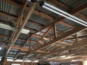
“If a single truss can carry 4 feet of roof, all things equal, then two of them (doubled together) can carry 8! … just make 2-ply trusses; each ply like the ones you can see here! Set them on the posts! Done.”
Miles: “I want a single-ply truss to drop between the laminations of a 3-ply post.”
(I tried to talk him into the 2-ply idea, without success.)
“Okay, my guess is … 2 x 8 rough sawn top and bottom chords, and more metal (probably twice as much) for the plates.”
Let’s do it.
(Selah)
Following are hand calcs to `solve’ Miles’ truss. I start with basic engineering mechanics … Method of `Pins’, or `Joints’, as taught in a typical 200-level college engineering course. The `connections’ of the lumber pieces of the truss are modeled as though smooth pins, or single through-bolts, with no resistance to the pieces rotating (in the plane of the truss) at the joints. Each joint (or pin) is analyzed for equilibrium under the actions of the adjoining lumber pieces pulling or pushing on the pin. Solution of the forces acting on each pin thus, by Newton’s Third Law, solves for the forces in the wood members … `pulling’ being tension, and `pushing’ being compression. I am taking you through a hand calculation for several reasons: 1) for my own practice; 2) for your illustration (especially if you’re a college student looking on); and 3) so I can use it to check more elaborate computer solutions of the same truss, or variants, later on.
Some notes getting started …
I am going to start with truss spacing at 4 feet, like in my shop, so that I can compare results on paper, with what is `real life’ over my head.
I am also going to use loading conditions presumably similar to those used (by someone, not me) for the original design of the shop trusses, specifically:
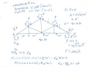
Downward (gravity) load = 20 pounds per square foot (psf), minimum roof construction live load, plus 5 psf dead load (weight of trusses and roofing materials … a light roof) = 25 psf.
This (25 psf) number is also a good starting place for a wind section uplift load … say 30 psf of pure wind uplift (suction) as a 90 mile-per-hour wind races over the roof, and the roof wants to fly away like an airfoil … minus the weight of the roof (5 psf) … giving 25 psf. Thus, for a `starting place’, the solution using 25 psf downward will also give me the solution for uplift, just with everything in reverse (members in tension under download will be in compression with uplift).
Pages 1 and 2 …
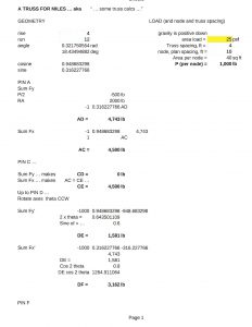
First I look at the loads as they apply to the truss. For the Method of Pins, the loads must be applied (also) at the pins. This might indeed be the case if the purlins holding up the actual roof material attach at the joints, or connections; otherwise applying the loads at the joints is a good (and necessary) first approximation. Each pin will carry the load (25 psf) times the tributary area (plan view) of roof carried by the pin (4 ft x 2 x 1/2 of 10 ft or 40 square feet) = 25 psf x 40 sq ft = 1000 pounds … say `P = 1000 lb’.
I look at the truss as a whole … the whole truss carries 1/2 P at one end, P at the three interior joints, and another 1/2 P at the other end … or 4P or 4000 lb. The truss is symmetric; the loading is symmetric, and the support conditions (walls at ends) are symmetric … so I could argue that the support (reactions) will be equal and up to 4P, or be 2P each … or I can go ahead and prove it (as in the calcs).
And then I start in on the Joints …
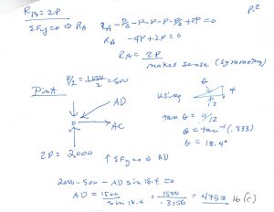
Note that I show force AD `pushing’ on Pin A. Thus, Pin A will be pushing on Member AD. This makes sense. A truss carrying download will tend to have the top (top chords or members) in `compression’, and bottom chords (bottom of truss) in tension. Had I computed a negative number, it would have immediately `raised a red flag`. The `(C)’ stands for `Compression’.
On across the truss …
Note that I (you) can only solve the truss by attacking, one at a time, joints that have no more than two unknown members. To solve a joint with, say, three members, you (I) need to first get the force in at least one of the three members, before I (you) can use the joint to get the other two.
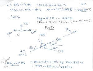
Note at Pin D I use a `rotated’ set of axes, to get DE directly. A bit more geometry, but at least I don’t have to solve two equations for two unknowns. Just my preference.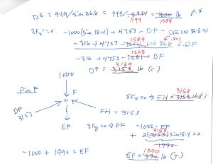
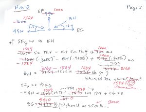
Yikes … on Page 4 you see some `red’. That’s because, on the first time through (`blue’), by the time I got to Page 5, things weren’t coming out quite right … my original calcs (on my cell phone) were a bit sloppy … the `red` numbers are corrected.
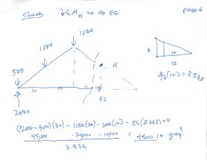
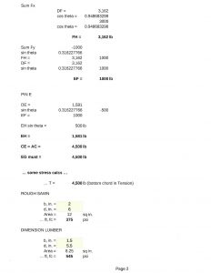
And on Page 6 you’ll see I do a check using the Method of Sections …
Now that I have proved to myself that I can still do the Method of Joints/Pins, by hand (and using the calculator on my cell phone, if necessary), I will leave it up to you to agree, or not, that the rest of the truss is a mirror image of the side I have now solved for.
(Rest)
Oh, let’s see if we’re in the ballpark with stresses in the lumber. The bottom chord of the truss being examined carries 4500 lb. The bottom chord of the truss in my shop will also need to carry, presumably, 4500 lb, and it’s a 2×6, dimension lumber.
The tension stress (f t) in the bottom chord will be the tension force (T) divided by the cross section area (A) …
where A = 1.5 in. x 5.5 in. = 8.25 sq in. (where 1.5 and 5.5 are the actual dimensions of the 2×6 nominal)
… f t = T / A = 4500 lb / 8.25 sq. in. = 545 pounds per square inch (psi).
The number (545 psi) appears reasonable for a working tensile stress of typical sawn dimension lumber.
(Stresses in lumber to be discussed in greater detail … MUCH GREATER DETAIL … in other posts.)
NEXT …
I decided to put together a quick spreadsheet, to be able to `tweak’ things, such as roof slope, truss spacing, and so on. The spreadsheet follows the hand calcs, so one checks the other.
Here it is for the trusses spaced 4 feet apart, with roof slope 4/12.
And, so now what’s cool, is that I can change things … for example, the truss spacing.
I don’t show the spreadsheet here, but, as one might guess, with the truss spacing doubled, everything else doubles.
I get a tension load in the bottom chords of … 9000 lb. If we guess that 2×8 dim lum would be required …
… f t = T / A = 9000 lb / (1.5 x 7.25 sq. in.) = 828 psi … that’s probably `workable’.
If Miles wants to use 2 x 6 rough …
… f t = T / A = 9000 lb / (2 x 6 sq. in.) = 750 psi … that’s probably doable.
If Miles wants to use 2 x 8 rough …
… f t = T / A = 9000 lb / (2 x 8 sq. in.) = 563 psi … that’s doable, but a heavier truss.
(Pause)
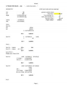
Now, what’s interesting, is that I went out and measured the rise/run for the trusses in my shop.
Turns out they are more like 3/12 … (56/240-ish) … and thus shallower.
The shallower truss will place a higher demand on the top and bottom chords.
Running through the spreadsheet … yeah, the bottom chord, instead of carrying 4500 lb under design load, carries 6429 lb.
The corresponding stress is …
… f t = T / A = 6429 lb / (1.5 x 5.5 sq. in.) = 779 psi … probably still `workable’.
Spreadsheet calcs follows:
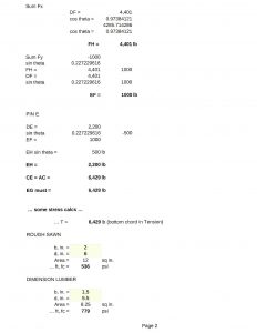
So, at this juncture, it looks like Miles can probably use 2×6 or 2×8 rough sawn for the top and bottom chords … depending on the `grade’ of the lumber.
… the loads in the members are …
Bottom Chords AC, CE, EG, and BG … all 4500 lb, TENSION
Top Chords AD and BH, … 4743 lb, COMPRESSION
Top Chords DF and FH … 3162 lb, COMPRESSION
King Post EF … 1000 lb, TENSION
Webs DE and EH … 1581 lb, COMPRESSION
Webs/Posts CD and GH … 0 lb (under the method of pins, simplification)
More to follow.
JRF