… and now for the headers
As an engineer I tend to design structures from the top down. First the roof loads, which determine rafters, or trusses, or whatever roof framing members. Then the beams/headers/girders supporting the rafters, then the columns or walls supporting the headers, and so on. Top-down load path. But that’s not the way the structure is built!
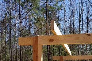
Now for the headers …
Starting from the top … we found that we’re going to use 2×6 rough sawn Southern pine rafters … spanning 12 feet, and overhanging 1 foot each end. The design was `governed’ by a concentrated load (construction worker) at mid-span of the rafter. The 2×6 rafter also accommodates a uniform construction load of 20 psf, as well as 25 or so psf of wind uplift. The barn has two 12-ft x 12-ft bays, and is `pole-barn’ construction, meaning the gravity loads (and lateral loads) are resisted (carried down … to the ground) by the posts/columns. `Headers’ (beams/girders/girts … whatever you want to call them) will support the rafters and transfer the loads to the posts/columns.
Each header will need to carry one set of ends from the rafters. In addition to the rafters spanning 12 feet, and overhanging 1 foot each, I need to have some kind of rake, so I’ll assume the headers also span 12 feet (the other direction, capturing the ends of the rafters), and (also) overhang 1 foot. Otherwise I’ll need to come up with some kind of outrigger system.
Let’s start out with the headers simply spanning 12 feet between posts/columns. This will be slightly conservative with respect to `bending’, since it ignores the counter flexure from the rakes. I’ll assume the roof weighs 5 psf (relatively light). In terms of a uniform, or line load, the headers will need to carry (between the posts) …
Dead Load …
w DL = (½ of 12 ft1 + 1 ft overhang) x 5 psf = 7 ft x 5 psf = 35 plf …
or
W = w x l = 35 plf x 12 ft = 420 lb … (dead weight of roof on the header span).
Live Load …
A single construction worker would contribute 300 lb live load … (probably won’t govern) …
A construction crew/operation will deliver … 7 ft x 20 psf = 140 plf … or 140 plf x 12 ft or 1680 lb2. (Yup, the whole crew governs over a single worker.)
Let’s look at the total … roof weight plus construction crew = 420 lb + 1680 lb = 2100 lb total load, uniform.
Check … total uniform `area’ load … 5 + 20 = 25 psf.
Total load to each header = uniform load x area supported by each header = 25 psf x [(½ of 12 ft + 1 ft) x 12 ft] = 25 psf x 84 sf = 2100 lb. Check.
Assuming the design of the header is `controlled’ by bending (stress) … let’s find the minimum Section Modulus needed.
In equation form …
Let fb = applied stress under load = Fb’ = allowable stress, where
fb = M / S,
and
assuming an allowable bending stress, Fb’, of … say, 1000 psi …
M = bending moment in header under design (applied) load = W L / 8 …
W = 2100 lb;
L = 12 ft;
8 = 8 …
M = 2100 lb x 12 ft / 8 = 3150 lb-ft.
Let’s get this into lb-in. …
3150 lb-ft x 12 in./ft = 37,800 lb-in.
Doing some rearranging …
fb = Fb’ = M/S … gives S needed …
S needed = M / fb = M / Fb’ = 37,800 lb-in / 1000 psi = 37.8 in.^3.
What sawn lumber (Southern pine) sections give me 37.8 in.^3???
Looking the the National Design Specification ® for Wood Construction (NDS) Supplement …
2 x 12 dimension lumber (1.5 x 11.25) … S = 31.64 … not enough.
Try 2 x 12 `actual’ … S = b h^2/ 6 = 2 x 12^2 / 6 = 48 … ENOUGH!
I will ask my son-in-law to cut me a 14-ft 2 x 12 (actual dims) header!
WAIT!
Several problems.
First, my son-in-law can cut sawn lumber in dimensions (actual) up to 6 inches, easily … 12 inches, more difficultly.
Also, I have been carrying the 2 x 6 rafters around … 14 ft long … and they are about all I can handle by myself … they are remarkably heavy; I think it’s because they are `GREEN’.
What are my other options?
2 x 10 actual … S = 33.3 … not enough.
4 x 10 actual … 67 … way enough.
4 x 8 actual … 43.7 … enough!
But that is still going to be heavy …
The `line weight’ of a wood member goes like … w = γ x A, where γ = specific weight, and A = cross section area. I could compare line weights, but I don’t know the specific weights of this `green lumber’ here3 … so let’s compare cross section area …
2 x 6 = 12 square inches (actual) … (I can lift into place)
4 x 8 = 48 square inches … that’s four times as much … will be four times as heavy … no way! I’m not going to ask my son-in-law to come over with his tractor to lift each header … if I can avoid doing so.
Hmmmm.
Try 6 x 6 … S = 36 in.^3. Enough! Actually, not quite … BUT … I’ll bet I’ll be able to split hairs, and make it work.4
Turns out A = 36 in.^2. Same number; different property.
At least my son-in-law can more easily cut the 6 x 6.
Or I can laminate three 2 x 6s side by side.
But still way to heavy to heave up above my head.
OMG! I don’t have to nail laminate the header together on the ground … this is what I’ll do … I’ll lift each 2×6 ply into place, one at a time … something I can do … and nail laminate them together once they’re up in place!!!5
*****
This `three’ is very interesting. Remember that the rafters span 12 feet … and that the headers themselves span 12 feet … same support condition … 12 foot span. And same load condition, … roof dead plus live load. The rafters are spaced 2 feet apart … so each header carries the ends of 12 ft / 2 ft per rafter = 6 rafters. Since the rafters are supported by headers at each end … we could say that each header carries half of 6 rafters, or the same as three rafters! A 3-ply 2×6 header will carry the ends of three 2 x 6 headers.
Interesting.6
Selah
The rest is easy … especially if we look at it in the context of a 3-ply 2×6 carrying 3 – 2×6’s. Deflection should be good. Shear should be good. Bearing should be good, as long as each 2 x 6 ply of the header has the bearing required for each of the 2 x 6 rafters … or the header as a whole has enough bearing … and so far, we’re way good in bearing. Let’s look!
BEARING!
Bearing (rafter on header) …
The roof is sloped, so I’ll bevel one of the lams of the 2×6 header to match the slope of the rafter. That means that the rafters will only actually bear on one ply of the header … but we already determined that would be fine … we assumed that we would have bearing area of at least 2 in. (width of rafter) x 1.5 in. (code min) … but the beveled lam of the header is 2 inches wide, … we’ll have 2 in. (width of header) times 2 in. (width of lam) = 4 sq. in. … way good!
JRF
___________________________
1 … in the direction of the rafter.
2Note that we don’t combine the concentrated single construction worker and the uniform construction crew … it’s either or … or … as we crunch along down through the structure, the worst of the two. It (the concentrated load) governed the bending stress limit state for the rafter … but will not govern the bending stress limit for the header (the uniform load representing the crew, materials, etc.).
3 … … plus the green weight is changing day by day as the lumber dries out.
4At the very least, I’ll be able to employ the repetitive member factor, Cr, since I have 3 plies … Cr is (at least) 1.15 for this condition … 1.15 x 1000 = 1150 psi. S needed = 37,800 / 1150 = 32.9 in.^3. I’ll have 36. Yay! (We’ll talk more about `allowable stress’ later.)
5This (3-ply) solution is not the most conservative with regard to wood mass … but just think! … I can proceed without employing additional labor (son-in-law and his sons), as well as machinery (his tractor). I’m thrilled that I can proceed with `just’ 2x6s … at my disposal. Plus, I am surrounded by Southern pine …
6We could also look at it like this … each rafter carries 2 ft x 12 ft = 24 ft of roof, at 12-ft span … and each header carries ½ x 12 x 12 = 72 sf of roof (okay, not counting overhangs) … 72 = 3 x 24 … if one 2 x 6 carries 24 sf of roof at 12 ft span, then 3 of them can carry 72 sf at 12 ft span. (This only plays out with this particular framing layout.)